Hydraulic Design and Project Planning Principles for Large-Diameter GRP Pipelines
Hydraulic Design and Project Planning Principles for Large-Diameter GRP Pipelines
In macro-scale infrastructure projects, the safe and efficient transportation of water, wastewater, or industrial fluids is a strategic engineering operation that leaves no room for assumptions and demands zero error tolerance. Particularly in mega projects where the nominal diameter (DN) reaches 4000 mm, the hydraulic and mechanical dynamics of the system fundamentally shift. In this context, the project planning of GRP (Glass Reinforced Plastic) pipelines ranging from 200 mm to 4000 mm in diameter necessitates the flawless integration of advanced hydraulic modeling and materials science, rather than merely being a basic pipe layout.
Offering an unparalleled strength-to-weight ratio due to their composite structures, large-diameter GRP pipes form the backbone of infrastructure in transmission lines, cooling water systems, and marine outfall projects with their high corrosion resistance and structural longevity. Compared to rigid materials (concrete, steel), the ultra-smooth nature of their internal surfaces prevents hydraulic capacity losses throughout decades of operational life. This hydraulic superiority, when evaluated in terms of both initial investment costs and Total Cost of Ownership (TCO) analyses, makes GRP pipes the most rational and economical choice for visionary engineering projects.
Fundamentals of Hydraulic Design and Engineering Calculations
As the diameter increases, the static and dynamic forces arising from the mass movement of the fluid increase exponentially. When executing the hydraulic design for GRP pipelines in the 200 mm to 4000 mm range, Hydraulic Grade Line (HGL) and Energy Grade Line (EGL) analyses must be conducted with meticulous precision. In an optimal design, it is ensured that the HGL does not intersect the topographical profile of the pipeline at any point.
Engineering expertise comes into play in the design of fittings, which constitute the most critical points of the system. Especially in custom applications within massive diameter ranges such as 1200 mm to 3200 mm, unbalanced thrust forces resulting from changes in direction at horizontal and vertical bends can reach hundreds of tons. To counteract these immense hydrodynamic forces, conducting rigidity analyses for thrust blocks or designing restrained joint systems is a mandatory engineering step for the mechanical stability of the pipeline.
Colebrook-White Formula and Friction Loss Analysis
Friction loss analysis is the most precise method for mathematically proving the hydraulic efficiency of GRP pipes. In turbulent flow regimes, the Colebrook-White equation, recognized as the primary reference in international AWWA and ISO standards, is essential for calculating the major impact of internal pipe roughness on pressure losses:
The absolute roughness value () of GRP pipes averages around 0.01 mm. This ultra-low roughness coefficient utilized in the formula minimizes the friction factor (). By enabling a reduction in the pumping head in pumped systems, this hydraulic advantage delivers millions of kilowatt-hours of energy savings throughout the project's lifespan.
Calculations for Water Hammer Effects
Water hammer, which occurs as a result of the sudden shutdown of pumps in the system or the rapid closure of valves, is the most critical hydraulic hazard in large-diameter pipelines. The magnitude of the pressure surge is calculated using the Joukowsky formula:
Here, the pressure wave velocity ( ), which dictates the fate of the system, is directly related to the modulus of elasticity of the material. Thanks to their composite and flexible structure, GRP pipes dampen this wave velocity ( ) by possessing a lower modulus of elasticity compared to rigid materials like steel. By acting as a natural cushion against sudden pressure increases (surge pressures), GRP pipes preserve the mechanical integrity of the system. In the advanced engineering design phase, the SN (Stiffness) and PN (Nominal Pressure) classes of the pipes are determined based on these transient analyses under a zero-risk principle.
Project Planning Based on Slope and Flow Requirements
The topographical structure of the pipeline route forms the foundation of hydraulic constraints and design. By performing diameter-slope optimization in free-surface or full-flow gravity pipelines, the flow velocity within the system is confined to a strict engineering safety corridor. The optimum success criterion in design is ensuring that the flow velocity does not fall below the minimum hydraulic carrying capacity required to prevent settling that could cause blockages in the system, while simultaneously not exceeding the cavitation/abrasion threshold that would damage the inner pipe wall. While low flow velocities increase the risk of sedimentation (solid particle settling) in the line, excessively high velocities trigger cavitation formation and abrasive wear on the inner surface, leading to pipeline fatigue.
Kuzeyboru, One of Turkey's Largest Manufacturers: R&D Center Approved Next-Generation Solutions
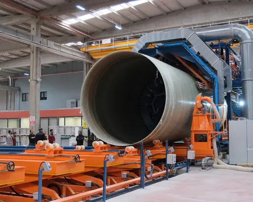
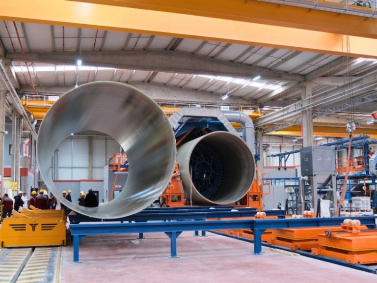
The flawless execution of engineering theories in the field depends on standardization, innovation, and laboratory capability in pipe production technology, extending far beyond mere manufacturing activities. Kuzeyboru, one of Turkey's largest manufacturers, is not merely a material supplier in the production of GRP pipes ranging from 200 mm to 4000 mm, but an authorized R&D center that designs specialized engineering solutions for macro projects.
Tensile tests compliant with ASTM D638 standards, hydrostatic pressure measurements conforming to ISO 1167 norms, and long-term (50-year) mechanical stability analyses conducted in Kuzeyboru laboratories certify the full compliance of the products with international quality metrics. The next-generation solutions developed through this robust R&D culture and advanced technology production infrastructure maximize the operational safety of infrastructure projects while providing expert engineers and project managers with absolute confidence at every stage, from hydraulic design to the on-site commissioning process.