What Is the GRP Pipe Installation and Fittings Selection Guide?
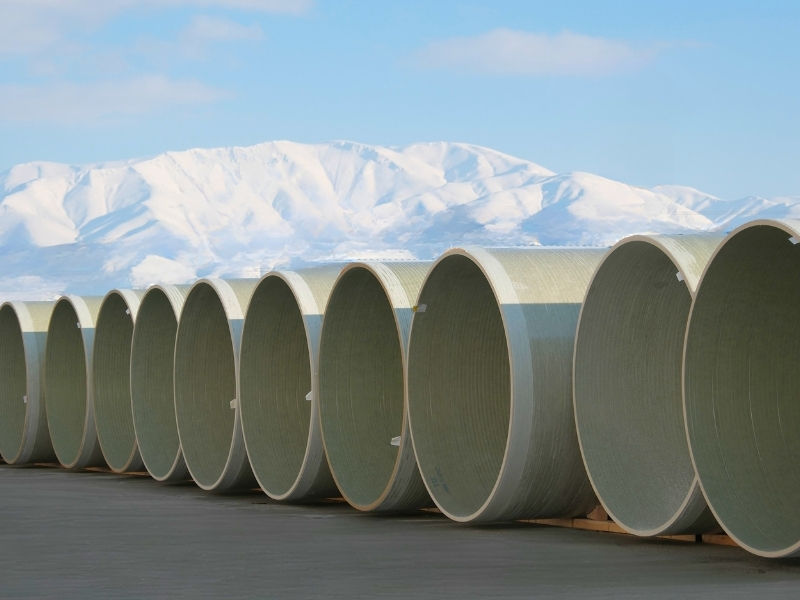
Glass Reinforced Plastic (GRP) pipes play a critical role in infrastructure projects thanks to their high corrosion resistance, superior hydraulic smoothness, and structural flexibility. However, for these composite systems to deliver their designed performance throughout their calculated service life, the correct application of GRP pipe installation principles in the field and the proper selection of GRP pipe fittings suitable for hydraulic and mechanical conditions are essential. This guide examines the technical details that must be considered, from pipe-soil interaction to hydraulic calculations.
Preparations for Proper Installation
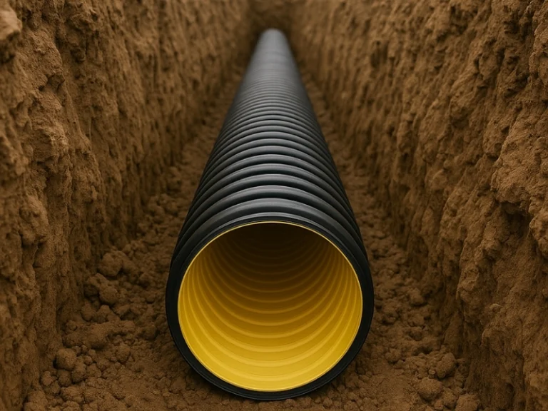
Since GRP pipes are classified as flexible pipes, they withstand static and dynamic external loads (soil, groundwater, traffic, etc.) not only through their own structure but also by dissipating these loads together with the surrounding soil. This structural behavior is known as pipe-soil interaction and requires trench excavation and bedding operations to be carried out with a high degree of engineering precision before installation.
The amount of horizontal deflection (displacement) and deformation that a GRP pipe may experience underground primarily depends on the combined performance of the pipe’s ring stiffness (SN) and the soil reaction resistance provided by the backfill material. To establish this structural balance, the bedding material must be selected according to project requirements, and the backfill must be compacted in stages. The compaction rate of the backfill material is determined by the gradation of the material used (crushed stone, gravel, sand, fine-grained soil) and the burial depth of the pipe. While 85% compaction may be sufficient for coarse-grained materials such as crushed stone or gravel, fine-grained soils are generally expected to achieve 90–95% of Standard Proctor density. The design performance of GRP pipes manufactured in accordance with ASTM D3262-20, ASTM D3517-24, and ASTM D3754-24 standards can only be achieved in a properly compacted backfill environment. Proper compaction maximizes the lateral support (passive resistance) capacity of the soil and keeps pipe deformation within safe design limits.
Trench Geometry and Cover Thickness: The trench width should be planned as a minimum of the pipe outside diameter plus 30–40 cm to allow sufficient compaction work on both sides of the pipe. For pipelines subjected to traffic loads, the minimum cover thickness above the pipe should generally not be less than 1.0 meter. The maximum burial depth should be verified through structural calculations based on the pipe’s ring stiffness class (SN 2500, SN 5000, SN 10000) and site soil conditions.
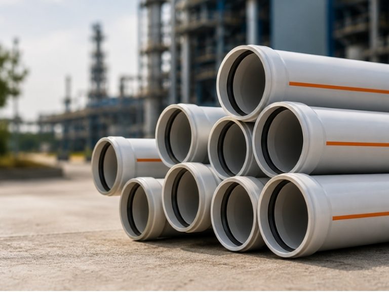
Basic Rules for Fitting Selection
The selection of fittings such as elbows, tees, and reducers used for changes in direction and diameter within pipeline systems must be carried out by considering the system’s operating pressure and the effects of water hammer.
In pressurized pipelines, the fluid exerts a hydraulic thrust force on fittings at points where the flow direction changes. If fittings (especially in coupling-type systems) are not properly restrained against this force, separation may occur within the pipeline. Therefore, concrete thrust blocks should be designed with sufficient dimensions to absorb the calculated force, or restrained fittings should be preferred.
Key Considerations for Leak Tightness
Leak tightness in GRP pipelines is generally achieved through double-socket couplings equipped with double-lip elastomeric gaskets (REKA, FWC, or equivalent). Since coupling types and tolerance values may vary by manufacturer, the relevant technical documentation provided by the manufacturer should always be consulted before installation. To ensure zero-leakage performance, the following technical procedures should be followed:
Tolerances and Deflections: During insertion of pipes into couplings, the maximum angular deflection limits specified by the manufacturer must not be exceeded. Although these values vary depending on coupling type and diameter, they are typically around 3° for DN300, 1.5° for DN700, and between 0.5° and 1° for DN1000 and larger diameters. As the diameter increases, the allowable angular deflection decreases; therefore, required changes in direction for large-diameter pipelines should be achieved using elbow fittings rather than angular deflection.
Gasket Positioning and Lubrication: It must be ensured that the gaskets are fully seated in the coupling grooves and adequately lubricated using the recommended assembly lubricant. Dry installation may cause gasket distortion and localized tearing under internal pressure.
Hydrostatic Field Testing: Before the pipeline is completely backfilled, partial backfilling should be carried out while keeping the joints exposed, and a hydrostatic pressure test should be performed in accordance with the procedures specified in ISO 23856 and AWWA C950-20 standards. The test pressure should be taken as either 1.5 times the design pressure (PN) or the design pressure plus 5 bar, whichever is greater. Test duration and acceptance criteria (allowable pressure loss limits) should comply with the relevant standards, and the results should be documented and recorded.
Horizontal Deflection Control: One of the acceptance criteria for installation is the horizontal deformation of the pipe. According to ASTM D3262-20, ASTM D3517-24, ASTM D3754-24, ISO 23856, and AWWA C950-20 standards, the measured short-term (initial) horizontal deflection after installation must not exceed 3% of the pipe's internal diameter, while the long-term horizontal deflection must not exceed 5%. These values should be verified and reported using mandrel testing or digital internal diameter measurement devices at designated control points along the pipeline.
Common Mistakes During Installation
Improper Backfill: Using non-standard aggregate sizes or sharp, angular stones in pipe bedding. This can create point loading on the pipe wall and lead to a punching effect.
Asymmetrical Compaction: Failure to compact the right and left sides of the pipe equally may cause the pipe cross-section to become elliptical, resulting in stress concentrations.
Excessive Pulling Force: Applying direct axial or lateral impact to the pipe with construction equipment during coupling installation may initiate micro-cracking within the composite matrix structure.