
Blog
Selecting HDPE Pipes from 20 mm to 1600 mm: How to Calculate Capacity Based on Diameter Measurements?
In infrastructure engineering, the efficiency of hydraulic networks is directly dependent on the thermodynamic properties of the fluid to be transported and the geometric characteristics of the selected pipe. High-Density Polyethylene (HDPE) pipes are indispensable products for modern fluid transfer systems due to their absolute resistance to corrosion, viscoelastic structure, and exceptionally smooth internal wall morphology. This blog post examines the hydraulic capacity calculations and engineering criteria behind selecting the correct polyethylene pipe diameter across a wide production range from 20 mm to 1600 mm.
Determining Diameter Based on Energy Capacity and Flow Requirements
The most fundamental step in designing a pipeline is determining the expected volumetric flow rate (Q) and calculating the internal diameter that will transport this flow at the optimum velocity. Diameter selection is formulated using the Continuity Equation, the basic rule of fluid mechanics:

In engineering practice, the optimum flow velocity (v) for potable water lines is generally limited to a range between 1.0 m/s and 2.0 m/s. Velocities that are too low lead to the settling of suspended solids (sedimentation), while velocities that are too high (especially above 3.0 m/s) intensify water hammer fluctuations and increase the risk of cavitation. Selecting the correct diameter involves finding the optimum cross-sectional area that safely conveys the target flow rate within these velocity limits.
Diameter Options from 20 mm to 1600 mm
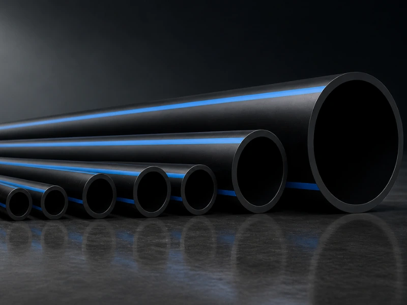
The diversity of infrastructure projects necessitates a very wide geometric production scale. Advanced extrusion technologies allow for standard HDPE pipe diameter measurements, which are divided into three main engineering categories based on the project’s mass flow requirements:
- Small Diameters (DN 20 mm – DN 110 mm): These are capillary distribution lines generally used in building sanitary plumbing connections, agricultural drip/sprinkler irrigation systems, and telecommunication fiber optic cable protection (corrugated or smooth).
- Medium Diameters (DN 125 mm – DN 630 mm): Standard infrastructure pipes used in the main arteries of urban drinking water networks, industrial process water transfer, and fire hydrant lines, resistant to high-pressure classes (PN 16 – PN 25).
- Large Diameters (DN 710 mm – DN 1600 mm): Macro-engineering structures with massive flow capacities used in giant main transmission lines carrying water from dams to cities, deep sea discharge (outfall) projects, and cooling water discharges for thermal/nuclear power plants.
Hydraulic Pressure Loss Calculations
As fluid moves through a pipe, it loses a portion of its hydraulic energy due to its own internal viscosity and friction against the pipe wall (Head Loss). The greatest advantage of HDPE pipes is that their absolute internal wall roughness value (k) is only around 0.007 mm (this value is 0.05 mm for steel and 1.0 mm for concrete). Continuous head losses in pressurized pipes are generally calculated using the Hazen-Williams Equation:

As understood from the formula, pressure loss is inversely proportional to approximately the 5th power of the pipe diameter.
Measurement Compatibility in Fitting Integration
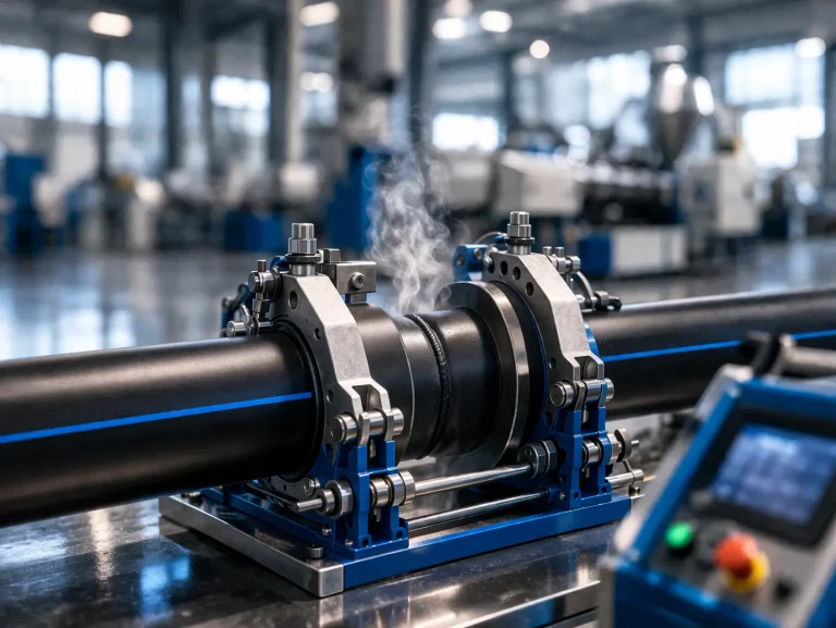
The most important element ensuring system integrity in HDPE pipelines is the jointing technology. During butt-welding or electrofusion processes, it is a thermodynamic necessity that the Standard Dimension Ratio (SDR = Outer Diameter / Wall Thickness) of the pipe and the fitting be perfectly compatible.
Two pipes with the same outer diameter (e.g., DN 500 mm) but different pressure classes (e.g., PN 10 and PN 16) will have different wall thicknesses, and therefore, different internal diameters (Di). This situation creates a “hydraulic step” at the welding interface, leading to turbulent flow and localized cavitation. Therefore, project design should be based not just on the outer diameter of the pipe, but on the SDR class to calculate the net internal diameter and fitting compatibility.
Project-Specific Custom Production Solutions
Beyond standard molds, every infrastructure project has its own thermomechanical and logistical realities. Kuzeyboru offers specific solutions for your projects through flexible and highly automated production lines:
- Size Optimization: The capability to produce single-piece lengths of 12, 13.5, or 15 meters—adapted to truck/ship logistical limits—to reduce the number of welds and labor costs.
- Color and Line Coding: Project-specific laser marking and color coding according to the intended use (yellow for natural gas, blue for drinking water, brown-striped for wastewater, or full co-extrusion surfaces).
- Offshore and Floating Line Applications: Leveraging the characteristic positive buoyancy of HDPE material to produce specific pipes resistant to hydrodynamic shocks for sea discharge and port dredging projects.
Related Articles

Which Insulation Methods Are Used to Prevent Water Noise and Vibration in Indoor Installations of PPR and PVC-U Pipes in Building Projects?
In modern building engineering, the acoustic comfort of living spaces is a design parameter as
What Is the GRP Pipe Installation and Fittings Selection Guide?
Glass Reinforced Plastic (GRP) pipes play a critical role in infrastructure projects thanks to
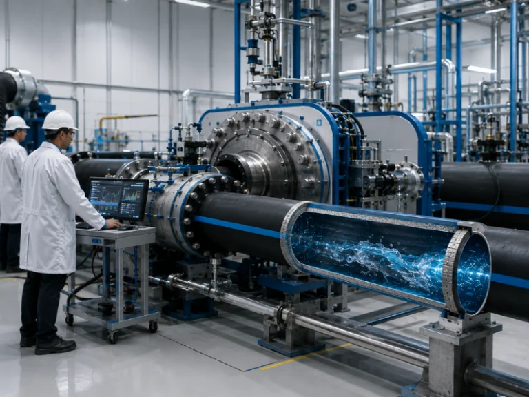
Quality Control Processes in Pipe Systems: Strength and Service Life Tests Conducted in Accredited Testing Laboratories
A pipeline’s ability to remain in service for 50 years—or even longer—begins with the tests
Related Articles
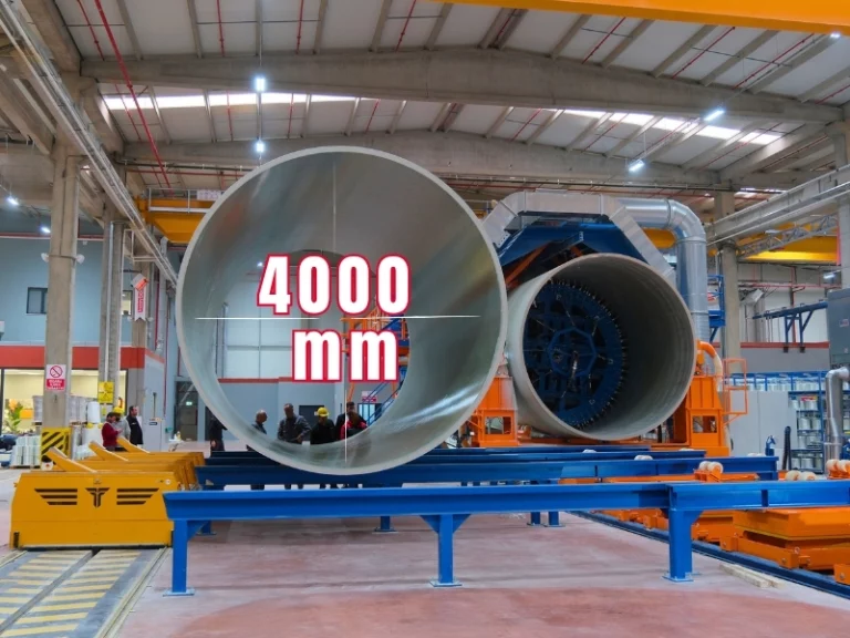
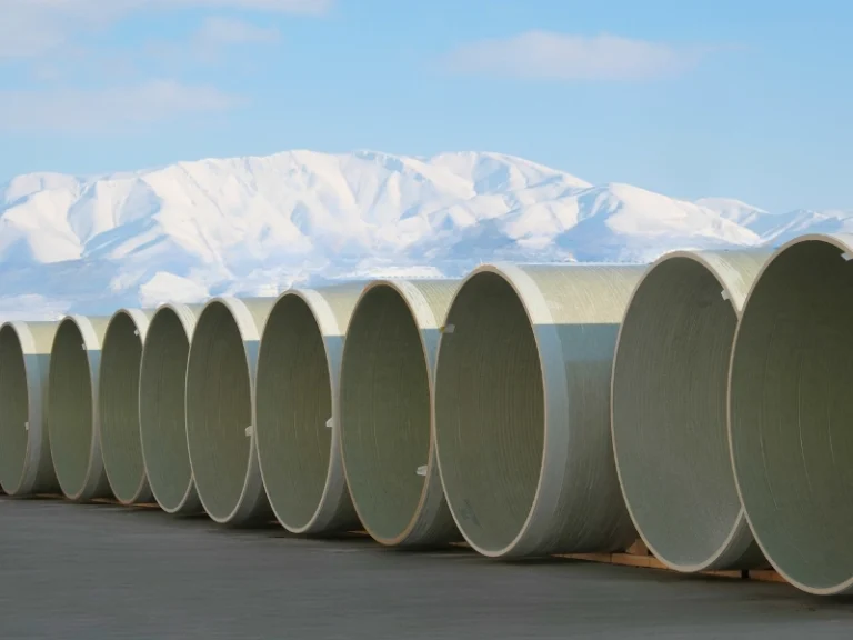
What are the GRP Pipe Diameters from 200 mm to 4000 mm and the Project-Specific Selection Guide?
Technical engineering guide on GRP pipe selection for infrastructure.

How to Repair a Cracked Plastic Pipe?
Compare professional plastic pipe crack repair technical methods.
How to Make Plastic Pipe Fittings?
Technical engineering guide on jointing methods in polymeric pipe systems.